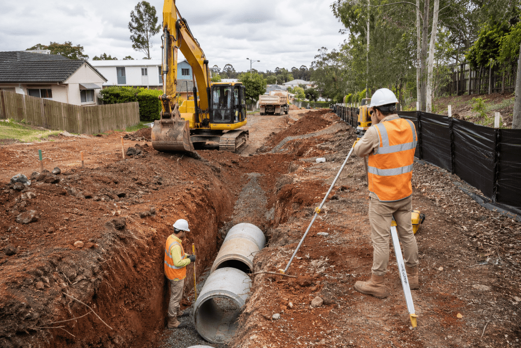
Why Drainage Is the Single Most Audited Item on a Logan Council Submission
Any developer who has lodged operational works applications across South-East Queensland will confirm a consistent pattern: drainage attracts more requests for information (RFIs), conditions, and post-construction inspections than any other civil discipline. Within Logan City Council’s jurisdiction—spanning from Springwood in the north through Marsden, Loganholme, Beenleigh, and down to the Coomera boundary—the scrutiny intensifies further. The reasons are grounded in topography, legacy infrastructure, and a planning scheme that explicitly prioritises stormwater management as a cornerstone of sustainable urban development.
Logan’s landscape presents a unique hydrological challenge. The Logan and Albert River catchments drain approximately 3,900 square kilometres of terrain ranging from the steep escarpments of the Scenic Rim to low-lying floodplains that historically experienced significant inundation events. Council’s drainage assessment officers understand that every new subdivision, every commercial hardstand, and every industrial shed roof incrementally increases impervious surfaces—and therefore peak discharge rates—into waterways already operating at capacity during major storm events.
From a compliance perspective, Logan City Council planning requires operational works applications to demonstrate hydraulic neutrality or, in many growth precincts, a net reduction in post-development flows. This isn’t a vague aspiration buried in planning scheme objectives; it manifests as hard conditions demanding QUDM-compliant modelling, approved detention systems, and stormwater quality treatment devices certified to specific pollutant removal targets.
The audit intensity extends beyond design approval into construction verification. Council-appointed superintendents regularly attend hold points for pipe bedding compaction, joint inspections on reinforced concrete pipe (RCP) installations, and as-constructed surveys confirming that built infrastructure matches approved drawings within millimetre tolerances. Non-conformances trigger rectification orders, and in severe cases, stop-work notices that cascade through project timelines.
For developers entering Logan from adjacent council areas, this rigour can catch teams off-guard. At Dynamic Earth Solutions, our work across Brisbane’s south and Logan has involved direct engagement with Logan’s drainage requirements across multiple project types. The difference between a smooth approval pathway and months of back-and-forth often comes down to front-end design integration and contractor execution that anticipates—rather than reacts to—council expectations.
The Logan Planning Scheme and How Drainage Fits Into Operational Works
Understanding where drainage sits within Logan’s planning hierarchy is essential before any design work commences. The Logan Planning Scheme, administered under the Queensland Planning Act, establishes the regulatory framework governing all development within the local government area. Unlike some councils that treat drainage as a secondary consideration to road geometry or lot yield, Logan explicitly elevates stormwater management to a primary assessment criterion for operational works applications.
Planning Scheme Structure and Stormwater Overlays
The scheme operates through a cascading structure of strategic outcomes, zone codes, and overlay maps. For drainage purposes, the critical overlays include:
- Flood Hazard Overlay: Mapped areas indicating defined flood events (typically the 1% AEP event) where development must demonstrate that flood levels are not adversely affected upstream or downstream.
- Waterway Corridors Overlay: Buffers around identified waterways requiring setbacks, vegetation retention, and often naturalised stormwater treatment trains rather than traditional piped systems.
- Stormwater Quality Overlay: Specifies treatment requirements based on receiving environment sensitivity, with catchments draining to Moreton Bay marine park attracting more stringent pollutant reduction targets.
When a development application triggers assessment against any of these overlays, the applicant must provide technical reports addressing specific performance outcomes. A subdivision in Yarrabilba, for instance, will face different overlay constraints compared to an infill industrial development in Slacks Creek—but both require drainage solutions that satisfy council’s engineering standards.
Operational Works Application Requirements
Operational works applications for drainage typically require:
- Stormwater management plan prepared by a Registered Professional Engineer Queensland (RPEQ)
- Hydraulic calculations demonstrating compliance with QUDM design criteria
- Erosion and sediment control plan aligned with IECA Best Practice guidelines
- Stormwater quality management plan identifying treatment devices and maintenance schedules
- Flood impact assessment where the site intersects mapped flood hazard areas
The application package must demonstrate that the proposed drainage system integrates with existing council infrastructure. This requires coordination with council’s asset management team to obtain connection approvals for discharge into trunk drainage networks—a process that can add weeks to approval timelines if not initiated early in the design phase.
Our team at Dynamic Earth Solutions regularly coordinates with hydraulic consultants during the design development phase to ensure that what gets approved can actually be built within site constraints. The disconnect between design intent and construction reality is a common source of variation claims and program delays. Understanding the planning scheme requirements before engaging contractors allows developers to brief civil teams accurately from day one.
Queensland Urban Drainage Manual (QUDM) — What Council Actually Checks
The Queensland Urban Drainage Manual represents the technical bible for stormwater design across all SEQ councils, and Logan applies it with particular thoroughness. Originally published by the Queensland government and progressively updated to reflect contemporary climate data and design philosophy, QUDM establishes the engineering standards against which every Logan drainage submission is assessed.
Design Storm Events and Critical Duration
QUDM specifies design storm events based on average recurrence intervals (ARIs) or annual exceedance probabilities (AEPs). For minor drainage systems—the pipe networks conveying frequent storm flows—Logan typically requires design to the 10% AEP (formerly 10-year ARI) event. Major drainage systems, including overland flow paths that activate during extreme events, must accommodate the 1% AEP (100-year ARI) flow without causing damage to property or risk to life.
Council assessment officers verify that hydraulic models use correct rainfall intensity data for the specific location. Logan spans multiple Bureau of Meteorology rainfall stations, and using Gold Coast IFD data for a Jimboomba site will trigger an automatic RFI. The critical duration—the storm duration producing the highest peak flow at a specific point—must be determined through iterative analysis rather than assumed.
Pipe Hydraulics and Velocity Limits
QUDM sets clear parameters for pipe system design:
- Minimum pipe diameter: 375mm for piped systems (smaller diameters permitted for allotment drainage only)
- Maximum flow velocity: 6m/s in reinforced concrete pipes to prevent scour damage
- Minimum flow velocity: 0.6m/s at design flow to ensure self-cleansing
- Pipe cover: Minimum 600mm for RCP under trafficable areas without special protection
- Pit spacing: Maximum 90m for maintenance access on pipes 600mm and below
Assessment officers cross-check submitted calculations against these parameters, and many applications are returned simply because the designer didn’t verify minimum velocities at the upstream extents of their system where contributing catchments are small.
Inlet Capacity and Bypass Flows
QUDM includes detailed methodologies for calculating inlet pit capacity based on approach flow depth, gutter gradient, and grate type. Council pays particular attention to bypass calculations—the flow that exceeds inlet capacity and continues downstream. Inadequate inlet capacity doesn’t fail an application outright, provided the design demonstrates safe conveyance of bypass flows to the next inlet or a defined overland flow path.
Where kerb-and-channel profiles deviate from standard configurations, additional calculations demonstrating inlet efficiency are required. Mountable kerbs, roll kerbs, and flush kerbs common in contemporary residential streetscape design all exhibit different hydraulic characteristics that must be accounted for in the modelling.
For civil drainage installation projects, our teams receive detailed pipe schedules and pit schedules derived from QUDM-compliant designs. Construction must then match design intent precisely—a pit installed 50mm higher than design level compromises the entire hydraulic gradient upstream.
Pre-Development Site Investigation and Catchment Analysis
Effective drainage design begins well before any pipes are selected or basins are sized. The pre-development investigation phase establishes the baseline conditions against which post-development performance is measured—and getting this phase wrong cascades through every subsequent design decision.
Understanding Existing Catchment Hydrology
Logan’s topography creates distinct catchment characteristics across different precincts. Sites in the northern corridor—Springwood, Underwood, and Rochedale South—typically drain toward Slacks Creek or Scrubby Creek tributaries, with relatively short catchment lengths and flashy runoff responses. The southern areas around Beenleigh, Eagleby, and Wolffdene drain toward the Albert River system through longer, flatter catchments where detention and attenuation become critical design considerations.
Pre-development investigations must establish:
- Existing impervious percentage: The baseline condition against which post-development changes are measured
- Overland flow paths: Where water currently concentrates during storm events, regardless of whether formal drainage exists
- Downstream receiving infrastructure: Capacity constraints in existing council networks that may limit permissible discharge rates
- Groundwater conditions: Seasonal high groundwater levels that affect pipe installation methods and long-term performance
- Soil infiltration capacity: Whether infiltration-based treatment systems are feasible given site-specific soil characteristics
Geotechnical Considerations for Drainage
Logan’s soil profile varies significantly across the LGA. The western areas around Flagstone and Jimboomba feature residual soils derived from metamorphic and sedimentary parent rock—typically reactive clays requiring specific trench backfill and bedding material to prevent pipe movement. Eastern areas near the bay, including Eagleby and Beenleigh, often encounter estuarine clay deposits with high plasticity indices and low bearing capacity.
Geotechnical investigations for drainage design should include:
- Borehole or test pit logs along proposed pipe alignments
- Laboratory testing for Atterberg limits and linear shrinkage on reactive soils
- Assessment of acid sulfate soil risk for sites below 5m AHD
- Compaction testing methodology recommendations for trench backfill
At Dynamic Earth Solutions, our complete civil services include bulk and detailed excavation for drainage works. We routinely encounter conditions on-site that differ from geotechnical predictions, and our operators are trained to recognise concerning soil behaviour and escalate to the project engineer before continuing excavation. This proactive approach prevents costly remediation and program delays.
Vegetation Assessment and Tree Protection
Logan’s significant tree overlay applies across much of the LGA, requiring applicants to demonstrate that development—including drainage infrastructure—appropriately manages impacts on regulated vegetation. Drainage alignments must be planned to avoid significant tree root zones where possible, or where avoidance isn’t feasible, include root-sensitive construction methodologies.
Where regulated vegetation affects drainage design, we coordinate with our sister company’s AQF-certified arborists in Brisbane to prepare arboricultural impact assessments that inform pipe alignment decisions. Their Arboricultural Impact Assessments identify tree protection zones (TPZs) and structural root zones (SRZs) that must be respected during construction.
The relationship between drainage installation and tree protection is governed by Australian Standard AS 4970 — Protection of trees on development sites. This standard mandates specific construction methodologies where trenching occurs within TPZs, including hand excavation, root pruning by qualified arborists, and installation of root-sensitive backfill.
Pipe Sizing, Pit Selection and Hydraulic Modelling
The core technical work of drainage design involves translating catchment analysis into a pipe and pit network that satisfies QUDM performance requirements while remaining constructible within site constraints. Logan council assessors review these calculations in detail, often requesting underlying model files to verify that submitted summaries reflect actual modelling outputs.
Hydraulic Modelling Methodology
Most drainage designs for Logan submission utilise DRAINS, XPSWMM, or TUFLOW modelling software—industry-standard platforms that implement QUDM methodologies computationally. The modelling must demonstrate:
- Pre-development flows: Peak discharge at key reporting points under existing conditions
- Post-development flows: Peak discharge after development, including any proposed detention or infiltration
- Hydraulic gradient line (HGL): Water surface profile through the pipe system at design flow, demonstrating adequate freeboard below pit surface levels
- Pipe capacity utilisation: Percentage of full-flow capacity used at design storm, with most councils requiring less than 80% utilisation to allow for blockage factors
Logan council has moved away from accepting simple rational method calculations for anything other than the most basic allotment drainage designs. Complex sites—particularly those with multiple sub-catchments, detention requirements, or stormwater quality treatment—require time-stepping hydrological models that capture the temporal distribution of rainfall and runoff response.
Pipe Materials and Grade Selection
The dominant pipe material for Logan subdivision and commercial drainage remains reinforced concrete pipe (RCP), typically Class 3 or Class 4 loading depending on cover depth and traffic loading conditions. Alternative materials—including PVC, PE, and polypropylene—may be accepted for specific applications but require separate approval from council’s asset management team, particularly for infrastructure that will vest to council ownership.
Pipe grade selection involves balancing competing constraints:
- Minimum grades to achieve self-cleansing velocity at design flow
- Maximum grades to prevent scour velocity exceedance
- Available cover to maintain minimum embedment while matching surface levels
- Connection levels at downstream discharge points
Where grades must be flatter than ideal—common in the low-lying eastern areas of Logan—additional pit access points may be required to facilitate maintenance, and gross pollutant traps become more critical to prevent sediment accumulation.
Pit Types and Junction Design
Logan’s standard drawing set specifies pit configurations for different network positions:
- Grated inlet pits: Cast-in-place or precast units with certified inlet capacity matching hydraulic calculations
- Junction pits: Providing access where pipes change direction, gradient, or diameter
- Gully pits: Receiving kerb-and-channel flow through side entry or combination inlets
- Access chambers: Larger pits on trunk drainage enabling maintenance equipment access
All pits must be designed for trafficable loads where located in roadways or carpark areas, with frames and grates meeting council’s approved product schedule. Non-compliant pit furniture is a common source of as-constructed inspection failures—our concrete and slab preparation crews are trained to verify pit specifications before installation.
Stormwater Quality Treatment Devices Logan Council Will Accept
Stormwater quality management has evolved significantly over the past two decades, and Logan’s requirements now mandate specific pollutant removal performance rather than simply requiring ‘a treatment device’. The planning scheme references the Model for Urban Stormwater Improvement Conceptualisation (MUSIC) as the accepted methodology for demonstrating compliance with stormwater quality objectives.
Pollutant Reduction Targets
For most development types within Logan, stormwater quality objectives align with state government targets under the Environmental Protection (Water) Policy:
- Total Suspended Solids (TSS): 80% reduction compared to untreated runoff
- Total Phosphorus (TP): 60% reduction
- Total Nitrogen (TN): 45% reduction
- Gross Pollutants: 90% reduction (typically achieved through screening devices)
These targets apply to the development site as a whole, allowing treatment trains to be optimised across multiple devices rather than requiring each individual system to achieve all targets independently. A typical commercial development might combine a gross pollutant trap at the site outlet with a bioretention basin treating the majority of runoff—together achieving the required reductions.
Acceptable Treatment Systems
Council maintains an approved products list for proprietary stormwater treatment devices, but also accepts performance-based designs that can demonstrate compliance through MUSIC modelling. Commonly accepted systems include:
- Gross Pollutant Traps (GPTs): Screening devices capturing litter, debris, and coarse sediment. Accepted products include Rocla CDS, Humes Netguard, and similar trash racks.
- Sediment Basins: Detention systems designed for settling velocity-based removal of suspended particles. Typically used for construction phase management rather than permanent treatment.
- Bioretention Systems: Vegetated filter media systems providing treatment through sedimentation, filtration, and biological uptake. Preferred for achieving nutrient reduction targets.
- Wetlands: Constructed wetland systems for larger catchments, providing extended detention and biological treatment through macrophyte uptake.
- Permeable Pavements: Infiltration-based treatment through specialised pavement systems, where site conditions permit adequate infiltration rates.
The selection of appropriate treatment systems depends on site constraints, catchment area, maintenance access requirements, and integration with the broader drainage network. Our bulk and detailed excavation teams have installed treatment systems ranging from compact proprietary GPTs requiring minimal excavation to large bioretention basins involving significant earthworks volumes.
Bioretention Basins, GPTs and the Move Away from Bare Detention
Logan council’s contemporary approach to stormwater management reflects a broader industry shift from pure detention—holding water back to reduce peak flows—toward treatment trains that address both quantity and quality objectives. The days of approval for bare concrete detention tanks with minimal treatment are largely over.
Bioretention System Design Requirements
Bioretention basins have become the workhorse of stormwater quality treatment in SEQ, and Logan has detailed design requirements reflecting hard-won lessons from early system failures. Key design parameters include:
- Filter media specification: Sandy loam with 5-15% clay content, minimum saturated hydraulic conductivity of 100mm/hr, organic content less than 5%
- Extended detention depth: Typically 300mm above filter media surface, providing additional storage volume and treatment contact time
- Submerged zone: Optional anaerobic zone below filter media supporting denitrification processes for improved nitrogen removal
- Transition layer: Coarse sand layer between filter media and drainage layer to prevent migration of fines
- Drainage layer: Gravel surrounding slotted underdrain pipes, conveying treated flows to the outlet
Council requires bioretention systems to include overflow structures sized for major storm events, preventing bypass of untreated flows during system surcharge. Maintenance access provisions—including hardstand access tracks for vacuum trucks and topped-up filter media delivery—must be demonstrated at the design stage.
Bioretention construction involves careful earthworks sequencing. Excavation to formation level, followed by placement and compaction of drainage layer materials, then filter media placement in controlled lifts, and finally landscape establishment. At Dynamic Earth Solutions, we coordinate bioretention construction with landscape contractors to ensure that civil works provide the correct platform for planting success.
Gross Pollutant Trap Selection and Installation
GPTs serve as the first line of defence in most treatment trains, capturing litter, coarse sediment, and organic debris before flows reach downstream treatment systems. Selection criteria include:
- Design flow capacity: Matched to the catchment area and connected impervious surface
- Maintenance access: Adequate clearance for gantry crane access or vacuum truck operations
- Sump capacity: Sufficient storage between maintenance events to prevent bypass
- Head loss: Hydraulic grade line impact on upstream drainage system
Installation of proprietary GPT units requires adherence to manufacturer specifications for bedding, backfill, and connection details. These systems often include specialised sealing gaskets and polymer components that can be damaged by incorrect installation procedures. Council inspectors verify compliance with manufacturer installation certificates at as-constructed inspection stage.
Integration with Detention Requirements
Where hydraulic neutrality requires on-site detention in addition to water quality treatment, contemporary designs integrate these functions through systems that provide both detention volume and treatment. Bioretention basins with extended detention, for instance, contribute to flow attenuation while delivering water quality improvements. Wetland systems similarly provide detention storage within the permanent pool and ephemeral zones.
Stand-alone detention basins—particularly concrete tanks with no treatment function—are increasingly difficult to approve without accompanying quality treatment elsewhere in the system. Council’s position reflects recognition that detention alone does not address the environmental impacts of urban runoff on receiving waterways.
Sediment and Erosion Control During Construction
Construction-phase stormwater management is as important as permanent treatment systems in Logan council’s assessment framework. The Environmental Protection Act imposes general environmental duty obligations on all construction sites, and council actively enforces compliance through site inspections and environmental audits.
IECA Alignment and Site-Specific ESC Planning
Logan requires erosion and sediment control (ESC) plans aligned with the International Erosion Control Association (IECA) Australasia Best Practice Erosion and Sediment Control guidelines. These plans must be prepared by suitably qualified professionals and include:
- Site assessment: Soil erodibility, slope length and gradient, drainage pathways, receiving environment sensitivity
- Control selection: Appropriate measures for the identified risk level (erosion hazard category)
- Design details: Standard drawings for sediment fences, check dams, sediment basins, and other control measures
- Staging plans: Sequencing of earthworks and progressive stabilisation requirements
- Monitoring and maintenance: Inspection frequency, maintenance triggers, and responsibilities
The ESC plan must be site-specific rather than generic. Plans that simply reproduce standard details without demonstrating how those measures address the specific site conditions will be returned for revision.
Sediment Basin Sizing and Construction
For sites with disturbed areas exceeding 2,500m², sediment basins are typically required to capture and treat construction runoff. Basin sizing follows IECA methodology based on:
- Catchment area draining to the basin
- Soil type and settling velocity of suspended particles
- Design storm event for capture (typically the 80th percentile 5-day rainfall depth)
- Sediment storage volume allowance between clean-out events
Sediment basin construction involves excavation to required volumes, installation of inlet structures to dissipate energy and distribute inflows, outlet structures incorporating primary and secondary spillways, and often floating oil/grease booms where hydrocarbon contamination risk exists.
Our site levelling and grading works incorporate ESC basin construction as an early-stage priority. Basins must be operational before major earthworks commence—a sequencing requirement that council auditors verify during initial site inspections.
Progressive Stabilisation Requirements
Logan council enforces progressive stabilisation requirements limiting the area of exposed soil at any time. Standard conditions require that disturbed areas be stabilised within defined timeframes—typically 10-20 days depending on slope and soil type—unless active construction is ongoing.
Stabilisation methods include:
- Hydromulching or spray-applied stabilisation products
- Erosion control blankets on steep slopes
- Aggregate surface stabilisation for haul roads and laydown areas
- Turfing or seeding for areas approaching final levels
The connection between drainage installation and ESC is direct. Trenching operations expose soil, and backfilled trenches are vulnerable to erosion until the surface is stabilised. Our teams schedule backfill compaction and reinstatement immediately following pipe installation to minimise exposure periods.
Compliance with WorkSafe Queensland excavation guidelines also applies during construction. Trenches must be appropriately battered or shored depending on depth and soil conditions—requirements that serve both worker safety and erosion control objectives.
Coordinating Drainage Installation With Bulk Earthworks and Concrete
Drainage installation rarely occurs in isolation. On most development sites, drainage works must be sequenced with bulk earthworks, road construction, building pad preparation, and concrete works. The coordination between these disciplines determines whether the project runs smoothly or becomes mired in interface conflicts and rework.
Sequencing Drainage Within the Earthworks Program
Optimal sequencing typically follows this pattern:
- Vegetation clearing and site establishment: Removal of vegetation within the disturbance footprint, establishment of ESC controls, and site compound setup. Where significant vegetation exists, land clearing Brisbane specialists should be engaged early. Tree stumps remaining after clearing require removal before bulk earthworks can proceed efficiently—we recommend All Sites Stump Grinding Brisbane for this preliminary work across Brisbane and Ipswich sites.
- Bulk earthworks—cut and fill: Major level changes to establish design surface levels. Trunk drainage alignments should be protected during this phase, with bulk fill kept clear of future trench zones where possible.
- Trunk drainage installation: Main drainage lines installed to design grades, with pit structures and headwalls. This work must occur before overlying road pavement or building pads are constructed.
- Road subgrade and pavement: Once drainage is in place, road construction can proceed with confidence that subgrade drainage and pipe crossing points are correctly positioned.
- Building pad preparation and detailed excavation: Lot-level drainage connections coordinated with building footings and service trenching.
- Concrete works: Kerb and channel construction, pit surrounds, and hardstand paving.
Deviation from this sequence—attempting to install drainage after road pavement is placed, for instance—results in costly saw-cutting, pavement reinstatement, and quality compromises.
Interface With Building Site Preparation
On residential subdivision sites, lot-level drainage stubs must be correctly positioned and capped for future connection by building contractors. Common interface issues include:
- Stubs positioned outside future building envelopes, requiring additional pipe runs
- Stub invert levels incompatible with building floor levels, preventing gravity drainage
- Unmarked or incorrectly located stubs, discovered only when building works commence
Clear as-constructed documentation and physical marking of drainage connection points prevents these issues. Our teams photograph and survey all stub locations, providing developers with records that facilitate smooth handover to building contractors.
Concrete Coordination for Pits and Headwalls
Drainage pits and outlet headwalls require cast-in-place or precast concrete elements that must be coordinated with broader concrete and slab preparation works. Critical coordination points include:
- Formwork timing: Pit formwork must be placed after pipe jointing is complete but before backfill operations obscure the connection point
- Reinforcement placement: Steel placement according to engineering specifications, with adequate cover to exposed faces
- Concrete placement: Coordinated with batching plant schedules to ensure adequate supply and placement windows
- Curing: Appropriate curing regime before backfilling or loading
Our footings and trenches capabilities integrate with concrete subcontractors to deliver complete pit installations ready for council inspection.
Compaction Verification Per AS 3798
Drainage trench backfill must be compacted to specifications compliant with Australian Standard AS 3798 — Guidelines on earthworks for commercial and residential developments. This standard, together with AS 1289 testing methodologies, governs the verification of compaction quality.
Logan council typically requires compaction testing at defined intervals along drainage trenches, with minimum relative compaction of 95% standard maximum dry density for trenches under trafficable areas. Test results must be provided as part of the as-constructed documentation package before practical completion certification.
At Dynamic Earth Solutions, our safety and compliance standards include documented compaction procedures with hold points for third-party testing. This systematic approach ensures that when council requests compaction records, we can provide comprehensive documentation demonstrating compliance at every point along the trench alignment.
Working With Council’s Inspection and Certification Process
Logan council operates a structured inspection regime for drainage infrastructure, with mandatory hold points that must be witnessed before work can proceed. Understanding this process—and preparing for inspections appropriately—prevents costly delays and reduces the risk of non-conformance notices.
Pre-Start Notification and Inspection Booking
Before drainage construction commences, the contractor must notify council and confirm:
- Operational works approval number and approved drawings on-site
- ESC controls installed and operational
- Materials on-site match specifications (pipe class, pit types, etc.)
- Setout survey completed by registered surveyor
Council inspection officers operate on booking systems with lead times—typically 48-72 hours notice for standard inspections. Projects that fail to allow adequate booking lead time risk idle plant and labour while waiting for inspector availability.
Mandatory Hold Points
Standard hold points for drainage construction include:
- Bedding inspection: Before pipe placement, verifying that bedding material type, thickness, and compaction comply with specifications
- Joint inspection: After pipe placement, verifying correct jointing technique, alignment, and joint material application
- Haunch/overlay inspection: After bedding around the pipe haunch, before full backfill proceeds
- Pit inspection: Before concrete pour for cast-in-place pits, or after precast pit installation verifying levels and connections
- Backfill compaction: Verification of compaction testing during backfill operations
- Final as-constructed: Survey verification that built infrastructure matches approved drawings within tolerance
Proceeding past a hold point without inspection approval constitutes a non-conformance. Council may require exposure of covered work to verify compliance—a costly exercise involving excavation, reinspection, and reinstatement.
As-Constructed Documentation
As-constructed surveys for drainage must be prepared by registered surveyors and submitted on council’s standard templates. Required information includes:
- Pipe inverts at all pits and changes of direction
- Pit surface levels (lid levels)
- Pipe diameters, materials, and grades between pits
- Outlet structure details including headwall levels and energy dissipation provisions
- Stormwater quality device locations and key levels
Tolerances for as-constructed surveys are tight—typically ±10mm for invert levels and ±50mm for horizontal position. Surveys that indicate out-of-tolerance construction trigger council review and potential remediation requirements.
For complex projects, we recommend engaging surveyors for progressive as-constructed captures rather than a single end-of-project survey. This approach identifies any drift from design intent early, when correction is straightforward, rather than at project completion when remediation becomes disruptive.
Developer Responsibilities Beyond Practical Completion
Drainage infrastructure vesting to council brings ongoing responsibilities during the maintenance period and beyond. Developers must understand these obligations before project handover to avoid unexpected costs and compliance issues.
Defects Liability Period
Logan council typically imposes a 12-month defects liability period following practical completion of subdivision infrastructure. During this period, the developer remains responsible for:
- Repairing any defects that emerge in drainage infrastructure
- Maintaining ESC controls until landscaping achieves adequate stabilisation
- Cleaning GPTs and sediment basins to remove construction-phase accumulation
- Replacing failed vegetation in bioretention systems
Bond security is held against these obligations, with release contingent on satisfactory final inspection at the end of the defects liability period.
Stormwater Quality Device Maintenance
For stormwater quality devices that remain in private ownership—common for commercial and industrial developments—ongoing maintenance obligations transfer to the landowner. Council conditions typically require:
- Maintenance in accordance with device manufacturer specifications
- Record-keeping demonstrating maintenance frequency
- Periodic inspection by qualified professionals
- Notification to council if devices become inoperative
Body corporates for community title schemes inherit these obligations, and smart developers ensure that body corporate establishment documents clearly identify maintenance responsibilities and budget allowances.
Connection of Future Stages
For staged developments, drainage infrastructure must be designed to accommodate future connections. This includes:
- Stub connections sized for ultimate upstream catchment, not just current stage
- Headroom in pit and pipe capacities for future flow additions
- Easement registration protecting infrastructure alignments through future development areas
Council assesses drainage applications for early stages against the ultimate development yield, ensuring that initial infrastructure isn’t undersized for later intensification.
Why Experienced Civil Contractors Matter for Logan Drainage
The technical requirements outlined throughout this guide demonstrate that drainage installation in Logan demands more than basic excavation capability. Contractors must understand council’s expectations, work within tight tolerances, coordinate multiple disciplines, and maintain documentation standards that satisfy rigorous inspection processes.
Plant and Equipment Requirements
Efficient drainage installation requires appropriate plant matched to pipe sizes and site conditions:
- Excavators: 8-14 tonne machines for typical subdivision drainage, larger units for trunk drainage in deep trenches
- Compaction equipment: Plate compactors for bedding and haunch zones, trench rollers for backfill layers
- Lifting equipment: Appropriate for handling RCP units (a 2.4m length of 600mm RCP weighs approximately 700kg)
- Survey equipment: Laser levels and grade checking equipment for maintaining pipe grades
- Dewatering equipment: Pumps and discharge management for trenches in high groundwater areas
Our fleet at Dynamic Earth Solutions includes purpose-selected equipment for civil drainage works, avoiding the compromises that come from repurposing general excavation plant for precision drainage installation.
Workforce Capability
Beyond equipment, effective drainage installation requires trained operators who understand:
- Pipe laying procedures including bedding preparation and joint techniques
- Grade checking and laser level operation
- Compaction requirements and testing coordination
- Safety procedures for trench work including shoring and benching
- Environmental controls and ESC maintenance
Our indigenous-owned business invests in workforce development, ensuring that team members progress from labouring roles into skilled operator positions with comprehensive civil construction understanding. This investment shows in work quality and in the smooth relationships we maintain with council inspection staff.
Coordination and Communication
Perhaps most importantly, experienced contractors bring project coordination capability that keeps drainage works synchronised with broader construction programs. This includes:
- Proactive communication with project managers about inspection requirements and lead times
- Coordination with hydraulic consultants when field conditions require design clarification
- Interface management with other trades working concurrently on-site
- Documentation systems that capture as-constructed information progressively
To discuss drainage installation requirements for your Logan development, contact our team. Our expanding South Brisbane operations position us to support projects throughout the Logan LGA and surrounding council areas.
FAQ — Drainage Installation Under Logan City Council
The following questions represent common queries from developers, builders, and consultants navigating Logan’s drainage requirements. For project-specific advice, consult with qualified hydraulic engineers and engage early with council’s development assessment team.
What minimum pipe diameter does Logan City Council accept for drainage in subdivisions?
Logan City Council aligns with QUDM requirements, specifying a minimum diameter of 375mm for piped stormwater systems that will vest to council ownership. Smaller diameters—typically 100mm or 150mm—may be used for allotment drainage within private property, but any drainage connecting to council infrastructure must meet the 375mm minimum. This requirement ensures adequate maintenance access and reduces blockage risk in public drainage networks.
Do I need a MUSIC model for a small commercial development in Logan?
MUSIC modelling is required for most development applications where stormwater quality treatment must be demonstrated. The threshold varies based on receiving environment sensitivity and development intensity, but as a general rule, any development adding more than 250m² of impervious surface should anticipate a MUSIC modelling requirement. Council assessors use MUSIC outputs to verify that proposed treatment systems achieve required pollutant reduction targets—submitting designs without supporting MUSIC modelling typically triggers requests for additional information.
How long does drainage approval take through Logan council?
Operational works applications for drainage typically progress through assessment within 20-30 business days where submissions are complete and compliant. However, incomplete applications—missing hydraulic calculations, non-compliant ESC plans, or insufficient supporting documentation—trigger information requests that reset assessment timeframes. Pre-lodgement meetings with council’s engineering assessment team can identify potential issues before formal application, streamlining the approval pathway. Complex sites with flood overlay implications or significant vegetation impacts may require longer assessment periods.
What compaction standards apply to drainage trench backfill in Logan?
Drainage trench backfill must comply with AS 3798 requirements, with council typically specifying 95% standard compaction (relative to Standard Proctor Maximum Dry Density) for trenches under trafficable areas. Backfill must be placed in controlled layers—typically 150-200mm loose thickness—with compaction verification at specified intervals. Testing must comply with AS 1289 methods, with results documented and provided to council as part of as-constructed certification. Non-compliant compaction can result in pavement settlement over trenches, a common defect that council actively inspects for during the maintenance period.
Can I use PVC pipe instead of concrete for subdivision drainage in Logan?
Alternative pipe materials including PVC and polyethylene may be considered for specific applications, but require separate approval from council’s asset management team for infrastructure vesting to public ownership. Factors influencing approval include pipe class rating, jointing methodology, long-term durability, and maintenance compatibility with council’s existing pipe inventory. Reinforced concrete pipe remains the default specification for trunk drainage and most subdivision applications. Early consultation with council is recommended before specifying alternative materials in design documentation.
What tree protection requirements apply to drainage installation in Logan?
Where drainage alignments pass within tree protection zones of regulated vegetation, construction must comply with AS 4970 requirements. This typically involves hand excavation within the TPZ, root pruning by qualified arborists (our sister company provides tree pruning expertise for these situations), non-destructive excavation techniques such as air-spading, and root-sensitive backfill specifications. Projects impacting significant trees should obtain consulting arborist reports during design development to inform alignment decisions and construction methodology.
How do detention requirements work for Logan developments?
Logan council requires developments to demonstrate hydraulic neutrality—post-development peak flows must not exceed pre-development flows at nominated reporting points. Where site development increases impervious surfaces significantly, on-site detention is typically required to attenuate peak flows. Detention volumes are calculated through hydrological modelling considering catchment area, impervious percentage change, and downstream infrastructure capacity. Contemporary designs often integrate detention with water quality treatment through systems like bioretention basins with extended detention depth, achieving both quantity and quality objectives within a single treatment train.
What happens if as-constructed surveys show drainage outside tolerance?
As-constructed surveys indicating drainage infrastructure outside specified tolerances—typically ±10mm for invert levels—trigger council review. Depending on severity, outcomes may range from notation with acceptance (minor deviations with no hydraulic impact) through to remediation requirements (significant deviations affecting system performance). Pipe grades flatter than design minimum are particularly problematic as they compromise self-cleansing velocity. Proactive verification during construction—checking levels at each pit before proceeding—prevents expensive post-construction remediation.
Do I need council approval to connect to existing drainage infrastructure?
Connections to council-owned drainage infrastructure require formal approval through the operational works application process. This applies whether connecting a new subdivision to existing trunk drainage or connecting a commercial development to roadside drainage systems. Connection applications must demonstrate that the receiving infrastructure has adequate capacity for additional flows, and that the proposed connection methodology won’t compromise existing system performance. Council’s asset management team assesses connection applications, and approval conditions often specify connection details, inlet treatments, and any required upstream works.
What qualifications do drainage design engineers need for Logan submissions?
Drainage designs submitted to Logan City Council must be prepared and certified by Registered Professional Engineers Queensland (RPEQ) with appropriate competencies in civil/hydraulic engineering. The Engineers Australia registration scheme and the Queensland Building and Construction Commission licensing framework govern professional practice requirements. Contractors installing drainage don’t require engineering registration, but must work under approved designs and coordinate with design engineers when field conditions require design modifications.
How do flood overlay requirements affect drainage design in Logan?
Sites intersecting Logan’s flood hazard overlay face additional assessment requirements beyond standard drainage approval. Flood impact assessments must demonstrate that development doesn’t adversely affect flood levels on surrounding properties—no increase in afflux upstream and no increase in velocity downstream. Floor levels must be set above the defined flood level plus freeboard (typically 300-500mm depending on flood hazard category). Drainage system outlets discharging into flood-affected waterways require energy dissipation and erosion protection measures. Queensland Reconstruction Authority guidelines inform flood-resilient design approaches for these challenging sites.
Can stormwater quality devices remain in private ownership?
Yes, stormwater quality treatment devices can remain in private ownership where they serve individual lots or private common property. This is common for commercial developments, industrial sites, and community title schemes where treatment systems are located on private land rather than public road reserves. Private ownership brings ongoing maintenance obligations to the landowner or body corporate, with council conditions requiring compliance with maintenance schedules and periodic reporting. For subdivision developments where treatment serves multiple lots, council may prefer public ownership with devices located within drainage reserves that vest to council at subdivision completion.
What are the requirements for dewatering during drainage construction?
Dewatering operations—pumping groundwater from excavations—require environmental management to prevent sediment-laden discharge reaching waterways. Standard requirements include settling treatment before discharge, monitoring of discharge water quality, and appropriate discharge points avoiding erosion or flooding of adjacent properties. For sites with potential acid sulfate soils (typically below 5m AHD elevation), additional requirements apply including pH monitoring and neutralisation treatment. Dial Before You Dig notifications should be completed before any excavation to identify underground services that dewatering operations might affect. Our guide to Dial Before You Dig in QLD explains how the enquiry, the locating and the potholing work in practice.
How do I find a civil contractor experienced with Logan drainage requirements?
Look for contractors with demonstrated experience in SEQ council work, appropriate equipment for drainage installation, and established relationships with council inspection staff. Supply Nation registration indicates indigenous-owned businesses meeting procurement standards—relevant for government and tier-1 contractor requirements. At Dynamic Earth Solutions, our work across Brisbane, Logan and Ipswich gives us direct experience with multiple SEQ council requirements. Browse our project insights or review our frequently asked questions for more information about our capabilities.